

Remove the fall hazard where you can. Where you cannot, guard it or keep the worker out of reach with travel restraint. That order is the hierarchy of controls, explained in OSHA: the law of the jobsite. Personal fall arrest is for the exposure that remains, and it has to have room to work. A fall arrest system does not stop a fall instantly. It needs distance to slow the worker down, and that distance has to exist below them.
Clearance is that space. This guide breaks a fall into its parts using the terms defined by the Z359 committee of the American Society of Safety Professionals (ASSP) in ASSP Z359.0-2023, then shows how those parts add up for an energy absorbing lanyard and for a self-retracting device in its common configurations, following the method in the self-retracting device standard approved through the American National Standards Institute (ANSI), ANSI/ASSP Z359.14-2021. It covers the United States, where the Occupational Safety and Health Administration (OSHA) sets the legal limits. Any real installation still has to be worked out for its own conditions, in accordance with the manufacturer’s instructions for the equipment in use.
The parts of a fall
Every fall arrest follows the same sequence. The worker falls freely until the fall arrest system begins to apply force, and the system then slows them to a stop. As it takes the load, the full body harness stretches and settles on the body. Each part of that sequence has a defined name, and the required clearance, often called total fall clearance, is those parts added together, plus a clearance margin.
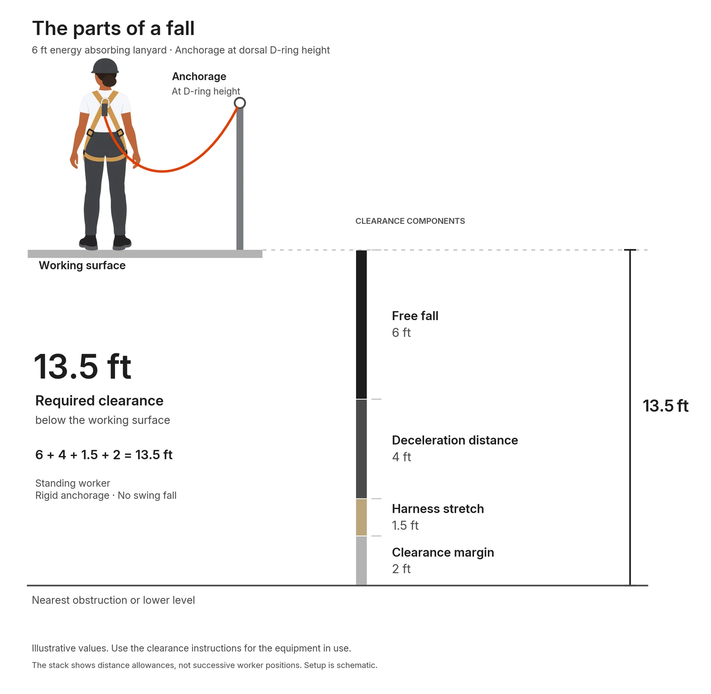
Free fall distance. How far the worker falls before the fall arrest system begins to apply force to stop them. With a lanyard, it lasts until the lanyard comes taut and the energy absorber starts to work. With a self-retracting device, it lasts until line begins to draw out of the device. The legal limits on free fall set by OSHA are further down this page.
Activation distance. On a self-retracting device, the line it pays out from the start of the fall until its brake begins to apply stopping force.
Deceleration distance. How far the worker’s harness attachment travels from the moment arresting force begins until it comes to a complete stop. On an energy absorbing lanyard, it is the energy absorber deploying, and the label states its maximum as the deployment distance. On a self-retracting device with an internal braking mechanism, it is the braking distance after the brake engages. Some self-retracting devices use an energy absorber instead of an internal brake, some rely on the stretch of the line itself, and some combine them.
Arrest distance. The term used for self-retracting devices: activation distance plus deceleration distance, the total vertical distance the device needs to stop a fall, as ANSI/ASSP Z359.14 defines it. It is the figure on the device’s label and in its clearance chart.
Total fall distance. How far the worker falls from the start of the fall until it is stopped: free fall plus deceleration distance, or for a self-retracting device, free fall plus arrest distance, plus any swing fall. ASSP Z359.0 notes that it is often measured by following the dorsal D-ring.
Harness stretch. How far the worker drops within the full body harness as it takes the load: the webbing stretching, the dorsal D-ring sliding up the back, and any slack being taken up. ASSP Z359.0 uses the wider term stretch out, which also covers the body straightening from a kneeling or lying start.
Clearance margin. The extra separation kept between the worker’s lowest point and the nearest obstruction below, at the lowest position reached during the fall arrest. ASSP Z359.0 lists it as the safety margin, and device instructions may say safety margin or safety factor. In this context it is a distance, not a strength ratio.
Required clearance. Measured below the working surface, total fall distance plus harness stretch plus the clearance margin. Measured from the anchorage it comes out larger, as the next section explains. Available clearance is the room that actually exists below the same starting point, and it has to be at least as large as the required clearance.
Different documents put one of these distances in a different place. ANSI/ASSP Z359.14 counts a self-retracting device’s activation distance inside its arrest distance. OSHA’s definition counts that same stretch of line as free fall. This page follows Z359.14, and it is one distance either way. Count it once, the way the instructions for your device count it: if the label gives an arrest distance, activation is already in it.
Where clearance is measured from
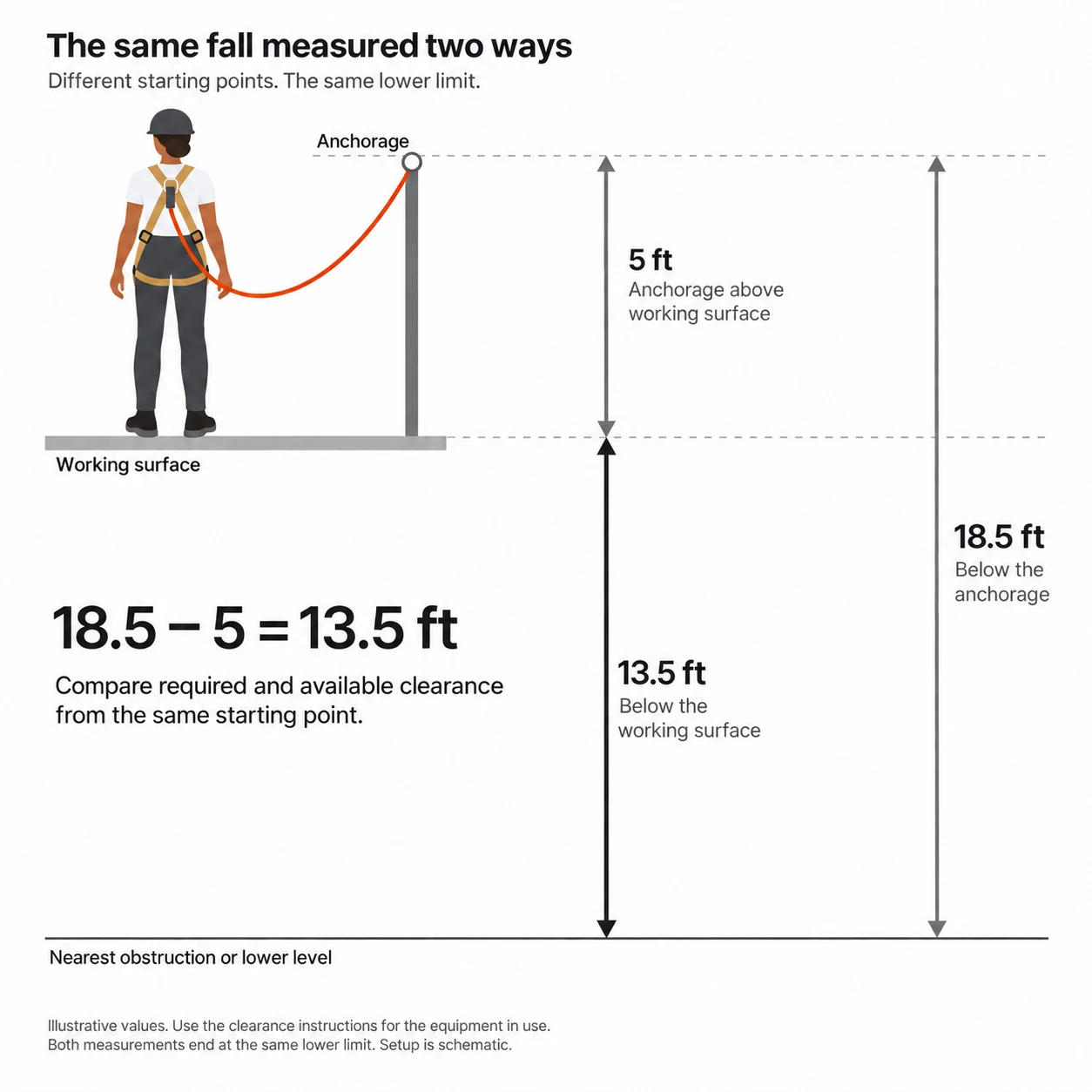
A clearance figure means nothing until you know its starting point. ASSP Z359.0 defines clearance against a stated starting point, giving the working platform and the anchorage as examples, and lists required clearance below the platform and required clearance below the anchorage as two separate terms. Manufacturers’ instructions use both. Some measure from the working surface, some from the anchorage, and some show both for the same product.
Fall Labs measures from the working surface, the surface the worker is standing on. It is the point you can stand on, see, and measure from, and it compares directly with the room you actually have below you. For a standing worker it also keeps the arithmetic relatively simple: the dorsal D-ring sits as far above the working surface as the worker’s feet hang below the D-ring, so a standing worker’s height does not need adding as a separate term. It still matters where it sets the free fall, as the sections below show.
If your instructions measure from the anchorage
That is a legitimate method, and done correctly it gives the same answer. Measured from the anchorage, the requirement comes out larger by exactly the height of the anchorage above the working surface, because the starting point is that much higher. In Figure 2, 18.5 ft below the anchorage, less the 5 ft the anchorage sits above the working surface, is 13.5 ft below the working surface.
Two habits keep the methods from being confused. Compare required and available clearance from the same starting point. And when two sets of instructions give different numbers for what looks like the same job, check the inputs before deciding either is wrong. Different arrest or deceleration distances, worker dimensions, stretch allowances, and margins give different totals even from the same reference point.
Working out the clearance you need
Required clearance below the working surface = free fall + deceleration or arrest distance + harness stretch + clearance margin
For a standing worker on a rigid anchorage, with no swing. Where the anchorage is off to the side, add the swing fall distance. Where the work is done kneeling, crouching, or lying down, add the extra body extension.
Which terms carry the weight depends on what connects the worker to the anchorage, and where that anchorage sits relative to the dorsal D-ring. Three configurations cover most work.
An energy absorbing lanyard
With a lanyard, free fall is real and usually the largest term. Start with the length of the lanyard and any anchorage connector, then look at where the anchorage sits compared with the dorsal D-ring. Level with the D-ring, free fall equals that length. For every foot the anchorage sits above the D-ring, free fall is a foot shorter. For every foot it sits below, free fall is a foot longer, so a lanyard anchored at the feet adds the full height of the D-ring above the working surface. The planned free fall also has to stay within the lanyard’s rating, which its label states.
Deceleration distance comes from the lanyard’s label, where it appears as the maximum deployment distance. ANSI/ASSP Z359.13-2013 (R2022), the standard for energy absorbers and energy absorbing lanyards, caps it at 48 in (4 ft) for a lanyard rated for 6 ft of free fall and 60 in (5 ft) for one rated for 12 ft. Those are the standard’s ceilings. The label on the lanyard in use is the number to plan with.
For the 6 ft lanyard anchored level with the D-ring in Figure 1, that comes to 6 + 4 + 1.5 + 2 = 13.5 ft below the working surface. The Field Insights article How to calculate fall clearance works through the same example step by step, with a worksheet for your own numbers.
A self-retracting device anchored overhead
ANSI/ASSP Z359.14 sorts self-retracting devices into two classes. Class 1 devices are for overhead anchorages only, with no more than 2 ft of free fall in practice. Class 2 devices are for work where an overhead anchorage is not always available, and are intended for up to 6 ft of free fall over an edge in practice. A device must meet the Class 1 requirements before it can qualify as Class 2.
With the device anchored overhead and no slack in the line, line starts to draw out the moment the fall begins, so the worker goes straight into the activation phase. Z359.14’s end-user guidance singles out the overhead anchorage as the easiest configuration to calculate and the safest one to use.
There is no separate free fall term here, and the reason matters. The travel before the brake engages is activation distance, and it is already inside the arrest distance on the label. Adding a free fall term on top would count the same distance twice. Slack in the line is the exception, because the worker falls through the slack before line starts to draw out.
Take the arrest distance from the device’s label and clearance chart. In the example, a 3.5 ft arrest distance, 1.5 ft of harness stretch, and a 2 ft clearance margin come to 7 ft below the working surface.
A self-retracting device anchored below the D-ring, and personal self-retracting lanyards
Anchor a self-retracting device below the dorsal D-ring, on the deck at a leading edge for example, and it behaves much more like a lanyard. As the worker starts to fall, the D-ring can first move toward the device rather than away from it, so the line retracts instead of drawing out, and the device cannot lock until line begins to extract again. That travel is free fall. Because the device takes up line as the worker drops, the free fall is typically less than a lanyard anchored in the same place would give, but it is not zero. Z359.14 notes it can be as much as 5 to 7 ft with a deck-mounted anchorage in leading edge work.
Only a Class 2 device should be used this way. Z359.14 says foot-level or deck-mounted tie-off should never be attempted with a Class 1 device, and calls for Class 2 below the dorsal D-ring. It is equally plain that the arrangement carries more risk even with the right device: its guidance warns that a foot-level anchorage greatly increases the risk of injury, and treats a fall over an edge as the last option for protecting a worker at height. The clearance is still worked from the working surface, and free fall now appears as its own term: free fall plus arrest distance plus harness stretch plus the clearance margin. Take both the free fall and the arrest distance from the device’s clearance chart for below-D-ring use, because they depend on the anchorage height, the setback from the edge, and the device itself. Class 2 devices are marked with their minimum installation setback and the clearance required for a fall over an edge. Where the line will bear on an edge, Z359.14 sends you to the manufacturer’s label and instructions for the clearance. The Class 2 test uses one prescribed edge, so the instructions also say which edges the device may be used over.
Personal self-retracting lanyards (SRL-Ps) follow the same logic. Z359.14 defines them as devices compact enough to be worn on the full body harness, and they are commonly used in place of an energy absorbing lanyard, often in a twin-leg configuration for 100% tie-off. The device rides on the harness and the worker connects the line to the anchorage, so where that anchorage sits relative to the D-ring decides the free fall, the same way it does for a lanyard. Anchored overhead, an SRL-P behaves like an overhead device. Anchored below the D-ring, it has real free fall, and only a Class 2 SRL-P should be used that way. Z359.14 shows hip-level anchorage of a Class 1 SRL-P as not recommended. Use the clearance values in its instructions for the anchorage position you are actually using.
| Configuration | Free fall | Deceleration or arrest distance | Harness stretch | Clearance margin | Required clearance |
|---|---|---|---|---|---|
| Energy absorbing lanyard6 ft lanyard, anchorage at dorsal D-ring height | 6 ft | 4 ftdeceleration distance | 1.5 ft | 2 ft | 13.5 ft |
| Self-retracting deviceOverhead, no slack. Class 1 or Class 2 | No separate termactivation is inside the arrest distance | 3.5 ftarrest distance | 1.5 ft | 2 ft | 7 ft |
| Self-retracting deviceBelow the D-ring, no edge contact. Class 2 only | From the device chart | From the device chart | 1.5 ft* | 2 ft* | Chart values plus 3.5 ft* |
| Self-retracting deviceBelow the D-ring, line over an edge. Class 2 only | Use the clearance marked on the device and its instructions for the actual setup. | Marked on the device | |||
Illustrative values for a standing worker on a rigid anchorage, with no swing. *Check which allowances the device chart already includes. Do not add them twice.
The numbers that go into it
Where each number comes from
Deceleration distance, arrest distance, and harness stretch come from the equipment: the lanyard’s label, the self-retracting device’s label and clearance chart, and the harness instructions. ANSI/ASSP Z359.14 requires a self-retracting device’s instructions to explain how to determine fall clearance, including a margin. Free fall, the anchorage position, and the available clearance come from the job. Before adding anything to a published clearance chart, check what it already includes, because some charts build in allowances you would otherwise count twice. The 42 in often quoted for self-retracting devices is a pass or fail limit in the standard’s drop tests, not a planning value. Use the arrest distance in the device’s instructions.
These values apply within the equipment’s rated capacity, which for Z359.13 lanyards and Z359.14 devices is 130 to 310 lb, including clothing, tools, and equipment. A worker outside that range needs equipment rated for their weight, and its label sets the numbers.
Where a label value is larger than a regulatory limit, the label value is the one to plan with. Under Z359.13, a 6 ft free fall lanyard can deploy up to 4 ft, more than OSHA’s 3.5 ft limit on deceleration distance (1910.140(d)(1)(ii); 1926.502(d)(16)(iv)). The two figures come from different test conditions, including different test weights. The OSHA figure is a compliance limit rather than a planning value, and the ANSI figure waives no OSHA requirement.
Harness stretch
ANSI/ASSP Z359.11-2021 limits harness stretch in its feet-first drop test to 18 in, or to the figure in the manufacturer’s instructions if that is less. That is a test pass criterion, so the planning value is the one in the harness instructions. The 1.5 ft used in the examples on this page is an assumed value of the kind a manufacturer states.
Posture
Clearance charts generally assume a standing worker, and so do the examples here. A worker who starts kneeling, crouching, or lying down straightens out during the fall and travels further before the system has them. ASSP Z359.0 includes that lengthening in its definition of stretch out, and ANSI/ASSP Z359.14 notes that these positions can change the outcome considerably and that a qualified person should be consulted. Plan for the posture the work actually involves.
Clearance margin
The clearance margin is the allowance for what the arithmetic cannot capture: a fall that does not go quite as the chart assumes, a measurement that is a little off, an obstruction sitting higher than expected. OSHA’s personal fall arrest provisions do not set a numerical margin. They require that the system prevent contact with a lower level. ANSI/ASSP Z359.14 requires the manufacturer’s clearance instructions to include one.
Fall Labs recommends never using less than 2 ft. Use more where the manufacturer’s instructions or the system design call for it.
The legal limits on free fall
Underneath every calculation sits an OSHA rule. In construction, Title 29 of the Code of Federal Regulations (CFR) requires a personal fall arrest system to be “rigged such that an employee can neither free fall more than 6 feet (1.8 m), nor contact any lower level” (29 CFR 1926.502(d)(16)(iii)). Both the construction and general industry rules prohibit contact with a lower level. General industry also expressly permits a free fall of more than 6 ft where the employer can demonstrate that the manufacturer designed the system to allow it and tested it to ensure the maximum arresting force of 1,800 lb is not exceeded (1910.140(d)(2)(ii)). The construction rule has no such provision. OSHA has interpreted it to accept a longer free fall only where the employer cannot provide a more suitable anchorage or other form of fall protection. Where limiting free fall to 6 ft is infeasible, the employer must limit it to the extent possible and ensure the arresting force does not exceed 1,800 lb (OSHA letters of interpretation, January 13, 2000 and September 21, 2007).
The equipment has limits of its own. The planned free fall must also be within what the lanyard or device is rated for. If the numbers do not fit the space below, the setup has to change.
Anchorage overhead: the biggest lever you have
Where the anchorage sits often moves clearance more than any other single choice. With a self-retracting device anchored overhead and no slack in the line, the whole stack stays short. Drop the anchorage to the worker’s feet and free fall alone can pass the legal limit before any equipment has been chosen. Fall Labs recommends tying off as high as the work allows, with overhead anchorage preferred unless a competent person determines it would create other hazards.
Foot-level tie-off, by the numbers. OSHA’s January 13, 2000 letter of interpretation, quoted again in its September 21, 2007 letter, works through a 6 ft lanyard anchored at floor level: the distance from the harness attachment to the floor, “usually 4 to 4½ feet,” plus the 6 ft lanyard, “which totals about 10 feet” of free fall. The exact figure depends on the worker’s height and where the D-ring sits, but it is past the 6 ft limit before deceleration is counted. In construction, OSHA accepts a setup like this only where the employer cannot provide a more suitable anchorage or other form of fall protection, with free fall limited as far as possible and arresting force at or below 1,800 lb. Where overhead anchorage is not possible, look first at travel restraint that keeps the worker from reaching the edge, and then at a Class 2 self-retracting device qualified for below-D-ring use.
Swing fall: the sideways hazard
Every calculation above assumes the worker falls straight down. When the anchorage is overhead but off to the side, they do not. The worker falls, the line comes taut at an angle, and they swing like a pendulum toward the point directly below the anchorage. ANSI/ASSP Z359.14 warns that a swing can add substantially to the total fall distance, and advises keeping the anchorage overhead and near the work.
Measured from the working surface, the reason is geometry. At the start of the swing, the line runs at an angle, so only part of its length reaches downward. At the bottom of the swing, the same length of line hangs straight down. The worker ends up lower than a straight fall would have left them, and that extra drop is the swing fall distance. ASSP Z359.0 measures it by following the dorsal D-ring from the start of the swing to its lowest point. In Figure 4, 10 ft of line with the anchorage 6 ft to the side reaches 8 ft down at the start of the swing and 10 ft down at the bottom: 2 ft of swing fall, added to the clearance required below the working surface.
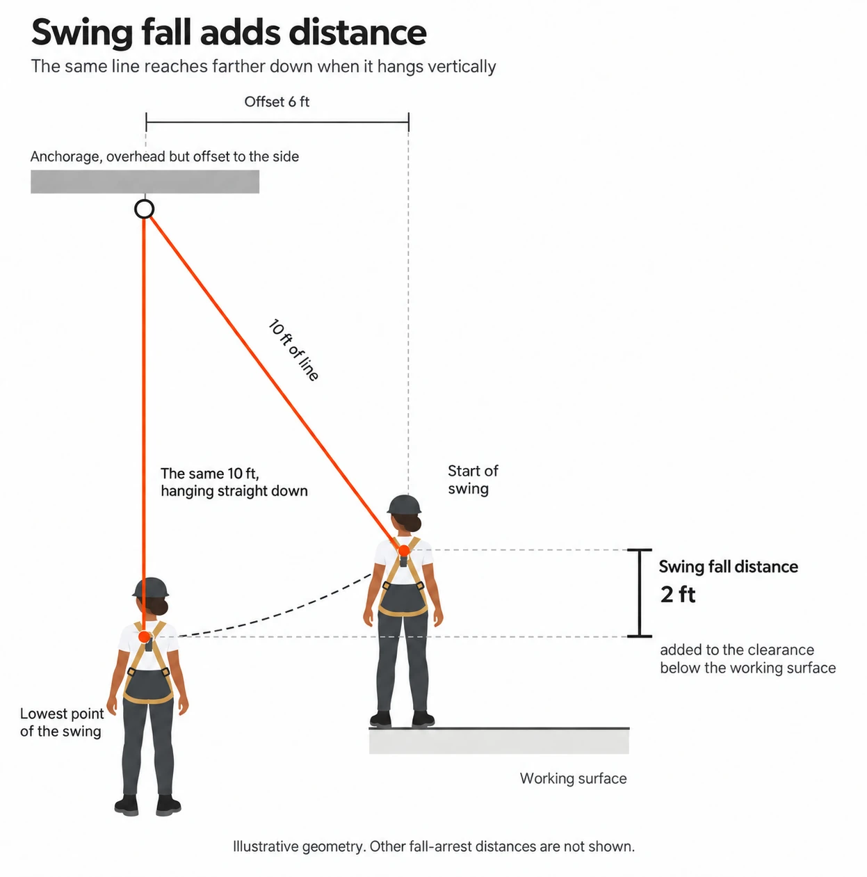
The swing also carries a strike hazard. A worker who swings into a column, a wall, or equipment in the path hits it with the speed built up in the fall and the swing. The mitigation is the same for both: keep the anchorage as close to directly overhead as the work allows, and add anchorages or devices rather than letting the worker range far to the side of one.
When the calculation is not this one
Every calculation on this page assumes an anchorage that does not move. Horizontal lifelines sag under load, some anchorage connectors are designed to deform, and a vertical lifeline stretches. In each case the system’s own movement adds to the fall, and the arithmetic here no longer covers it. ANSI/ASSP Z359.14 says that movement has to be taken into account with a qualified person’s input, and names ANSI/ASSP Z359.6, the standard for the design of active fall protection systems, as a resource with detailed clearance guidance. Z359.6 is written for the qualified person designing the system rather than for the person using it, and a system of that kind should be designed and documented by one.
Putting it together
Before the work starts:
- Find the working surface and measure the available clearance below it to the highest obstruction in the fall path, not just to the ground.
- Note where the anchorage sits relative to the dorsal D-ring, and whether it is directly overhead or off to the side.
- From the instructions for the equipment in use, take the clearance for that configuration. If they give the parts instead of a total, take the free fall, the deceleration or arrest distance, and the harness stretch.
- Make sure the clearance margin comes to at least 2 ft, counting any margin the chart already includes, and add swing fall and body extension where they apply and the chart does not already include them.
- Compare the two. If the required clearance is more than the available clearance, change the setup, not the arithmetic: a higher anchorage, equipment made for that position, or a different fall protection method altogether.
